Service Editor

The editor-service-deployment Service Editor supports you in managing your Service Deployments.

Open Service Editor

CTRL + SHIFT + D, S

Service Interfaces

The communication of an Adaptive platform is service oriented in nature, which means its functionalities mainly consist of Services being consumed and provided among its components. The element Service Interface is the means to model access to these functionalities, as the Services are made available through method, events, or fields. It also ensures compatibility between components by formalizing what kind of information these Services will be expected to exchange.

Service Deployment

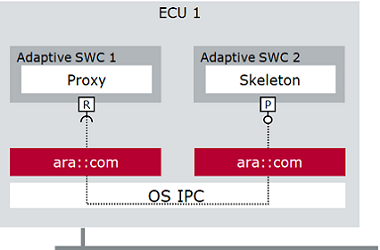
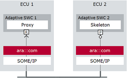
Depending on where two communicating Software Components are located, different forms of communication bindings are more preferable. For instance, when the communication takes place between two Software Components on the same machine, IPC (Inter-Process Communication) would be appropriate, while SOME/IP would be more appropriate for communication spanning between two different machines.

inter-process-communication

some-ip-communication

Inter-Process Communication

SOME/IP Communication

The communication to be used can be defined by the element Service Interface Deployment, which is also used to set a unique ID with which the Service can be identified.

Service Instances

When a Service described by a Service Interface shall be deployed, an instantiation of it must be modeled. A Service Instance is represented by either required or provided Service Instance elements. Depending on which communication to use, different types of instances must be modeled, for example Provided SOME/IP Service Instance. Using mappings, the Service Instance can be allocated to the Machine and Process which will provide or consume the Service. The Service Instances are also given a unique ID, which is used for identification on the network.

Open Editor

To open the Service Editor, expand your DaVinci Adaptive project in the DaVinci Project Explorer and double click on da-vinci-developer-adaptive Open Project Dashboard. The Project Frame opens showing the Project Home. You can then open the Service Editor as follows:

  • Open the editors Editor menu on the top right of the Project Dashboard and click the editor-service-deployment Service Editor command.

  • Alternatively, use the context menu command editor-service-deployment Service Editor of the da-vinci-developer-adaptive Open Project Dashboard node in the DaVinci Project Explorer.

  • Alternatively, on the Dashboard page of the Project Home, click editor-service-deployment Service Editor in the Comfort Editors area.

  • Alternatively, on the Dashboard page of the Project Home, click the arrow of the Current Focus drop-down list and select Machine Integration. In the Service Interface Deployments area, click the Edit button (this requires at least one created Service Interface Deployment).

  • Alternatively, use the context menu command editor-service-deployment Open in Service Editor of a Service Instance, Service Instance To Port Prototype or Machine Mapping, Service Interface, or Service Interface Deployment in the AUTOSAR Model Explorer.

The Service Editor opens in a new tab of the Project Frame.

Functionality

The Service Editor provides the functionalities listed below. If not otherwise mentioned, the functionalities available in the details-mode-form-mode Form mode are described.

If you want to manage the properties of an element textually, switch to the dml-editor DML mode via the toolbar and refer to DaVinci Modeling Language Editor for more information.

Tree View Structure Description of Functionalities

services <Service Interface>

Select a Service Interface in the tree view on the left side of the editor.

The form page provides the following options:

  • Name: Displays the name of the Service Interface.

  • Description: Displays the description of the Service Interface.

  • Method: The tab Method displays all Methods and their Arguments for the selected Service Interface. You can add, clone or delete Methods.

    • add Add Method: Click this icon to add a new Method to the Service Interface and define a new Argument.

    • add-multiple Clone Method: Click this icon to clone the selected Method.

    • delete Delete Method: Click this icon to delete a selected Method.

    • Configure Transformation Properties.

  • Event: The tab Event displays all Events for the selected Service Interface. You can add, clone or delete Events.

    • add Add Event: Click this icon to add a new Event to the Service Interface.

    • add-multiple Clone Event: Click this icon to clone the selected Event.

    • delete Delete Event: Click this icon to delete a selected Event.

    • Configure Transformation Properties.

  • Field: The tab Field displays all Fields for the selected Service Interface. You can add, clone or delete Fields.

    • add Add Field: Click this icon to add a new Field to the Service Interface.

    • add-multiple Clone Field: Click this icon to clone the selected Field.

    • delete Delete Field: Click this icon to delete a selected Field.

    • Configure Transformation Properties.

  • Deployments: Lists the Service Interface Deployments for this Service Interface. The table displays the name, type, ID, and version of the Service Interface Deployments. The fields of the table are read-only. Modifications must be done on the page of the respective sub-element. You can add or delete Service Interface Deployments as follows:

    • add Create Service Interface Deployment: Click this icon to open a dialog in which you can define a new Service Interface Deployment.

    • delete Delete Service Interface Deployment: Click this icon to delete a selected Service Interface Deployment.

tree-view-structure-child-elementservice-interface-deployment-some-ip <SOME/IP Service Interface Deployment>

Select a SOME/IP Service Interface Deployment in the tree view on the left side of the editor.

At the top of the form page, the general properties are displayed and can be modified:

  • Name: Displays the name of the SOME/IP Service Interface Deployment. Edit the field to change the name.

  • Description: Displays the description of the SOME/IP Service Interface Deployment. Edit the field to change the description.

  • General Configuration: Displays the type, ID, major, and minor version of the SOME/IP Service Interface Deployment. The ID, major, and minor version can be changed via double click on the respective field.

Deployment Configuration Area

The Deployment Configuration area contains the tabs Methods, Fields, Events, and Event Groups of the SOME/IP Service Interface Deployment. You can modify the Deployment Configuration as follows:

  • Methods: Double click on a field to open a dialog in which the value can be modified.

  • Fields: Double click on an ID field (Get Name, Set Name, or Notify Name) to open a dialog in which the values can be modified.

  • Events: Double click on a field to open a dialog in which the value can be modified.

  • Event Groups:

    • add Create Event Group: Click this icon to open a dialog in which the name of the new Event Group can be defined.

    • delete Delete Event Group: Click this icon to delete a selected Event Group.

    • Name: Lists the name of the Event Groups. Expand an Event Group to show the Events it contains.

    • Mapped: Displays whether an Event is mapped or not. Expand an Event Group and activate the check box of one or more Events to be mapped. Deactivate a check box to unmap an Event.

    • Event Group Id: Displays the ID of the Event Groups. Double click on the field to change its value.

Instances Area

The form page provides the following options:

  • Instances: Lists all Services Instances of the SOME/IP Service Interface Deployment. You can modify the Instances as follows:

    • Click add Create Service Instance: Click this icon and follow the Create Service Instance wizard to create an Service Instance. Modifications of the Service Instance can be done on the respective subpage.

    • Click delete Delete Service Instance: Click this icon to delete a selected Instance.

tree-view-structure-child-elementtree-view-structure-child-elementservice-instance <SOME/IP Service Instance>

Select a SOME/IP Service Instance in the tree view on the left side of the editor.

At the top of the form page, the general properties are displayed and can be modified:

  • Name: Displays the name of the SOME/IP Service Instance. Edit the field to change the name.

  • Description: Displays the description of the SOME/IP Service Instance. Edit the field to change the description.

  • SD Server Config or SD Client Config: You can modify the SD Config as follows:

    • reference Select Reference Target: Click this icon to select or modify the reference to the SD Config.

    • skeleton-model-wizard Create Reference Target with the Skeleton Model Wizard.

    • edit Edit: Click this icon to open a dialog in which the referenced SD Config can be modified.

    • go-to-reference-target Go to Reference Target: Click this icon to open the referenced SOME/IP SD Config in the AUTOSAR Model Explorer.

  • Instance Info: Displays information on the selected Service Instance. You can modify the settings as follows:

    • Provided Instance Id or Required Instance Id: Double click in the field and enter a new ID.

    • Required Minor Version: This setting is only available for Required Service Instances. Double click in the field and enter the required minor version. Enter ANY if any version is accepted.

Load Balancing (Optional) Area

This area is only available for Provided Service Instances. Use the [+] icon to expand the Load Balancing area. You can enter the Priority and Weight for the selected Service Instance.

Provided/Required Event Groups

For each event group in the service interface deployment, an event group element in the provided/required service instance can be created. These elements allow configuration of multicast and timing.

Mappings Area

The Mappings area contains a tab for Machine, Port, and Signal Mappings. You can modify the Mappings as follows:

  • Machine: The Machine tab allows to map Machines to the Service Instance.

    • add Add Machine Mapping: Click this icon and follow the Create Service Instance To Machine Mapping wizard to create a new Service Instance to Machine Mapping.

    • Edit Endpoints: Double click on the respective field in the table to edit a TCP/UDP Endpoint.

    • Edit Ports: To edit a TCP/UDP Port, a TCP/UDP Endpoint must be created first (see Edit Endpoints). After the endpoint was created, the TCP/UDP Port can be modified by double clicking on the respective field in the table.

  • Port: The Port tab allows to map Ports to the Service Instance.

    • add Create Port Prototype Mapping: Click this icon and follow the Create Port Prototype Mapping wizard to create a mapping.

    • edit Edit: Click this icon to edit the selected Port Prototype Mapping.

  • Signal: The Signal tab allows to map a Signal to the Service Instance.

    • add Add Service Instance To Signal Mapping: Click this icon to open a dialog in which a Signal Mapping for this Service Instance can be selected. To create or modify a Service Instance To Signal Mapping, refer to the Signal-To-Service Editor.

General Functions

  • delete Delete: Click this icon to delete the properties of a respective field or a selected element, respectively. For fields that reference an element, only the reference is deleted but not the referenced element itself.

MICROSAR Adaptive Parameters Area

This area contains MICROSAR Adaptive Parameters that are specified as Model Extensions (MEX) in the MICROSAR Adaptive BSW Package. Parameters for the selected AUTOSAR model element are displayed in the table of the MICROSAR Adaptive Parameters area on the respective pages of the Service Editor. Select a parameter in the table to view the editing options.

For more information on the MICROSAR Adaptive Parameters, refer to the Technical Reference in the .\Doc\TechnicalReferences folder of your MICROSAR Adaptive BSW Package.