Execute and Test a Virtual ECU in CANoe
Run and test a built virtual ECU (vECU) in CANoe by adding it as a node component and mapping its communication channels to the CANoe network.
-
A built vECU (for example, a DLL or shared object).
-
A CANoe configuration with the target network available.
-
Add the vECU as a node-layer component of a network node. In the Node Configuration window, add the DLL as a component of the node. Alternatively, you can reference the vECU via a VMODULE file. In general, this node doesn’t need a CANoe interaction layer, because the virtual ECU handles all bus communication.
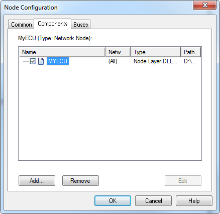 Figure 1. Referencing a Modeling Library in a Node in CANoe
 -
Configure the channel mapping so the vECU’s communication controllers map to the correct CANoe network channels. In the Simulation Setup tab in vVIRTUALtarget, set the Network Names to specify which communication networks are available in the simulation—they must match the network names in CANoe.
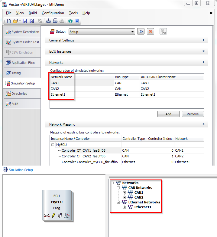 Figure 2. Channel Mapping: Bus Name Configured in DaVinci Configurator Classic Must Match the Network Name in CANoe
|
When you load the vECU, vVIRTUALtarget registers any system variables the virtual ECU defines, and they become visible in CANoe. You can access the system variables in, for example, test units, panels or CAPL code, for automated or interactive tests. 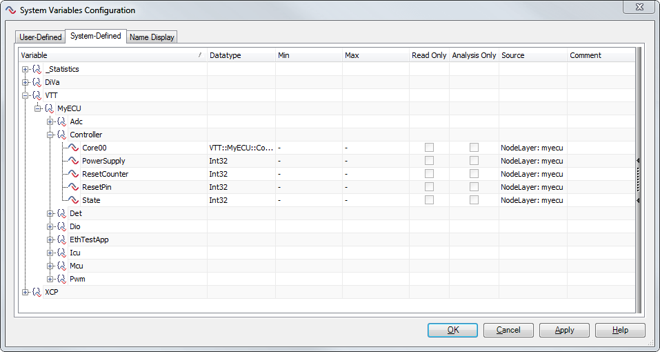
Figure 3. System Variables of a virtual ECU that are automatically registered in CANoe
|
System Variables Reference
The respective Technical References of vVIRTUALtarget MCAL modules explain the MCAL modules' system variables. The Controller namespace contains several system variables for the emulated controller’s status.
| System Variable | Description |
|---|---|
|
Shows the error reason of the last error in the core |
|
Shows the current state of the core. |
|
Use this variable to enable or disable the power supply. Disabling and enabling the power supply restarts the ECU. |
|
Counts the number of resets since the last measurement start. |
|
Switching this value to 1 resets the ECU. |
|
Shows the simulation state of the ECU in CANoe. |
CANoe Working Modes
CANoe has three possible working modes, shown below. In Real Bus mode, CANoe can communicate with real buses via a network interface, and the virtual ECU runs as an additional, simulated node in parallel. In Simulated Bus mode, CANoe can operate without hardware, and it simulates all buses completely.
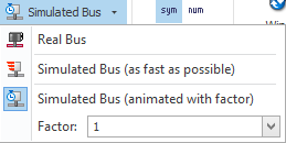
In Simulated Bus mode, you have two options:
-
As fast as possible
The simulation doesn’t run at a constant speed; it runs as fast as possible. Performance depends mainly on your computer’s performance and the simulation’s complexity.
-
Animated with factor
The simulation runs at a constant speed according to the given factor. The factor value either slows down (factor > 1) or speeds up (factor < 1) the measurement.